Kalman Filter Object
Overview
A Kalman filter is a mathematical tool used for estimating the state of a system based on noisy and incomplete information. It's often used in navigation systems, like GPS, as well as in control systems, like self-driving cars.
Imagine you're driving a car and you have a GPS device that tells you your location. However, the GPS signal is sometimes lost and the readings are also a bit noisy, so you don't always know exactly where you are. The Kalman filter can help estimate your location by combining the noisy GPS readings with other information, like the speed and direction of the car, to give you a more accurate estimate of your location.
The filter does this by making use of two things: a prediction of what the state of the system (in this case, your location) will be in the future, and an update step that takes into account the new information and adjusts the prediction. This process is repeated over and over again, so that the estimate of the state of the system gets more and more accurate as time goes on.
Kalamn Filters will allow you to reduce the nondeterministic error you get in your measurements,
and make your autonomous more accurate. Nondeterministic error is the error that is not constant,
which is often enough to make your autos suck. The parameters for a Kalman filter are R and Q,
the process noise and measurement noise. These are in whatever units you use for the measurement.
But just what are these measurements and how do I tune it?
The process noise (R) is how much noise is in the actual system.
This characterizes the system, it's what's actually happening in the real world. This can be caused by a ever-so-slight jitter in the motor or fluctuations in battery voltage, or any number of things actually.
The measurement noise (Q) is how much noise is in the system output. This is caused due to slight
inaccuracies that are inherent in all sensors/systems, and can become pretty significant over time.
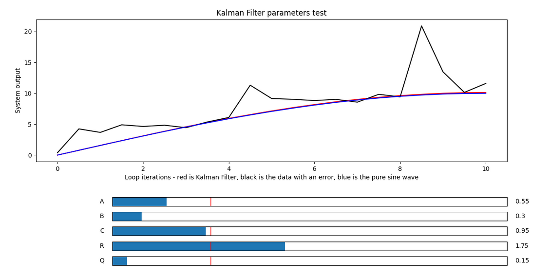
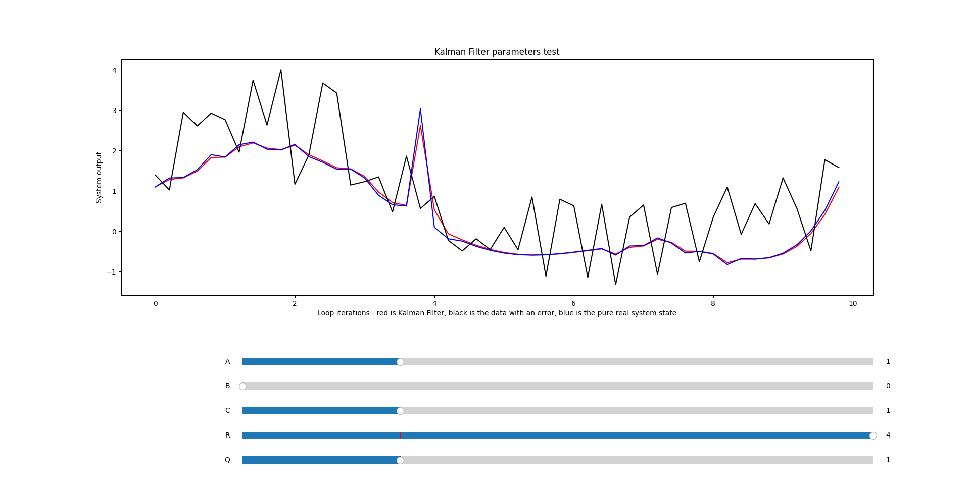
To tune these, first look at a graph of the system output on FTCDashboard. You can view it by adding the output data to multiple telemetry:
- Java
- Kotlin
mTelemetry.addData("System state", system.getState());
mTelemetry.addData("System state", system.state)
Then, look at the data and measure the amplitude(half the distance from peak to valley of the error) of the noise while running a simple program on the system that you know what the output should be. What makes the tuning process difficult is that amplitude is comprised of both the measurement error and system error so... yea not that easy :(
However, you can assume a 50/50 split and assign the process noise to half of the amplitude and measurement noise to the same as well. From there, try adjusting each value in both directions to try and optimize further. If using this technique, generally the best direction to start is increasing the noise values.
Or, you could just guess based on the range of the numbers you'll be dealing with - Kalman filters are incredibly powerful, and if you know your system well enough you should be able to reduce system state error by several factors. It's not as calculated as the previous strategy, but it should work pretty well too.
Just show me how to use it already...
Here's how to implement one:
- Java
- Kotlin
KalmanFilter systemKF = new KalmanFilter(R, Q);
system.setState(systemKF.filter(system.getState()));
val systemKF = KalmanFilter(R, Q)
system.state = systemKF.filter(system.state)
Okay, so yes lots of nested functions here but all that's really going on is that the Kalman filter
is being updated with the current system's measured state in systemKF.filter(system.getState())
and the new system state is just being set to whatever that output is.
It's pretty simple, nothing too crazy here. Feel free to use @Config or @ConfigKt to tune these
in dashboard easier, while looking at the plot of the system state.
Motion Models
You can also specify a motion model as a lambda with an extra argument in the constructor, here's what the motion model takes in/puts out:
typealias MotionModel = (Double, ElapsedTime) -> Double
It takes in the system state as the first argument and the time since the Kalman Filter has started through the second element, and is used as the motion model inside the Kalman Filter. The default model is a simple linear one. For more information on motion models, look at the resources provided at the bottom of the page.
Keep in mind that modelling complex systems may be, well, complex, and that the basic linear system can work pretty well.
Use Case Example:
Below is some modified lift code from Power Play, in which a PIDF controller is determining the
amount of correction to apply to the lift motor power in order to correct the error between
liftHeight (the current system state) and targetHeight, but the new motor power including the
correction is passed through a Kalman filter, that then sets the motor power to the filtered value.
You can apply this approach to all your mechanisms to improve the accuracy and decrease jitter in
your mechanisms! Sometimes, PIDF can be very challenging (or actually impossible) to tune given
different systems, and so this approach can help you come up with a working solution!
- Java
- Kotlin
double correction = liftNormalPID.calculate(liftHeight, targetHeight);
double filteredCorrection = liftFilter.filter(liftMotor.power + correction);
liftMotor.setPower(filteredCorrection);
val correction = liftNormalPID.calculate(liftHeight, targetHeight)
val filteredCorrection = liftFilter.filter(liftMotor.power + correction)
liftMotor.power = filteredCorrection
More Resources:
[https://engineeringmedia.com/controlblog/the-kalman-filter]
[https://www.bzarg.com/p/how-a-kalman-filter-works-in-pictures/]